Richard’s Shop

Constructing a Cheap Dividing head
Richard 2005
A dividing head is an accessory for accurately and repeatably rotating a piece of work through a small angle, for example to rotate a gear blank by the angle of a single tooth. Dividing heads are usually used with milling machines for making gears, reamers, etc. The problem with dividing heads is that they tend to be expensive.
A less expensive alternative to a dividing head is a spin indexer, which can also be used to rotate work through a small angle. The problem with spin indexers is that they limit your choice of angle.
The goal of this project is to build a dividing head from an inexpensive spin indexer and parts borrowed from the Gingery dividing head project. The main advantages of this approach, from my point of view, are that the large spindle bore of my spin indexer allows it to use 5C collets, and that the fraction plates and cranking handle from the Gingery dividing head can be used with the new unit interchangeably.
The Spin Indexer
A few years ago I bought an Enco spin indexer. They are available for about $30. The indexer is solidly built and accepts 5C collets. The collets are available for as little as $6 each and have a range of about 1/16” to 1 1/8” for round work. I bought several popular sizes. (5C collets are also available for hex and square work, but not for $6!)
The indexer has served well for jobs where the divisions come out to even 1-degree values.
The Gingery Dividing Head
I had also previously built the Dave Gingery’s dividing head and a selection of fraction plates to use for jobs involving fractions of degrees. The Gingery design is most useful as a rotary table.
For those who don’t know, the design is described in Dave Gingery’s book #6: Build Your Own Metal Working Shop From Scrap -- The Dividing Head and Deluxe Accessories (ISBN 0-9604330-5-8, available from Lindsey).
You can use Gingery’s book as a guide to make the parts needed to add fractional dividing capability to the spin indexer and to make it possible to use some of the parts like fraction plates and the driving crank handle interchangeably.
Hint: I often use a computer printout of a hole circle or degree wheel taped to the Gingery fraction plate to adjust strange angles. This is fine for when one does not want to make and drill a fraction plate.
The Project
The project uses
-
•The hand-crank from the Gingery dividing head,
• One or more fraction plates from the Gingery dividing head, and
• An ENCO (or similar) spin indexer.
You’ll need to build
• A fraction plate holder,
• A worm carrier,
• A frame to mount the above to the spin indexer,
• A worm wheel,
• A worm gear, and
• A shaft for the worm gear.
The idea of the dividing head is to accurately reduce a large rotation of the crank (as measured by the fraction plate) into a small rotation of the spindle. In this design (following Gingery) the reduction is 40:1 -- a 40 degree rotation of the crank handle is reduced to a 1 degree rotation on the spindle, etc.
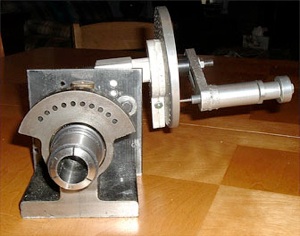
The following photo should give a pretty good idea of how things go together.
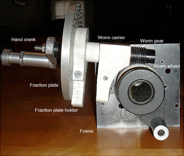
The above picture shows the major parts of the finished project. The frame is made of a flat iron plate. The worm wheel, worm carrier, and fraction plate holder are PVC. The worm gear is Delrin.
The Worm Wheel
The required lead for the worm wheel teeth for my setup is at least 0.2”. This is dictated by a number of factors including the I.D. required for the wheel to fit my indexer spindle (they are not all alike), the materials on hand, and the desire to stay with the 40:1 ratio of the Gingery design.
But, for cutting the worm wheel, I had only a homemade 1/2-10 Acme tap with a 0.1” lead. I used this to make an 80-tooth worm wheel. (The 40:1 reduction can still be obtained by using a double-threaded worm gear as described later.) So let’s go!
The spin indexer spindle O.D. measured 1.75” so I fabricated a blank disk by gluing 3 pieces of 1/4” PVC from flattened schedule 40 pipe and milled a hole large enough to clear a set collar which is part of the spin indexer assembly. I then fastened the blank to the end set collar with 3 screws at 120 degrees, slipped the thing on the 5C spindle mounted it on the 7x12 lathe between the 4 jaw chuck on one end and a 60 degree center held in an appropriate collet (hiding inside a socket spacer) on the other end. Thus the blank was trued and sized right on its spindle. The set collar on the spindle has 3 radial screws as well to grab the spindle shaft.
I gashed the worm wheel blank using a slitting saw to form slots which will allow the acme tap used as a hob to grab and assure only 80 teeth.
The Frame
The frame is held to the right end of the indexer casting by a couple of bolts after drilling and tapping the casting.
The Shaft, Fraction Plate Holder, and Worm Carrier
The shaft carries the fraction plate (via the plate holder) and worm gear. It rotates within the worm carrier by which it is attached to the frame. All these parts are described in Gingery’s Book 6.
The Worm Gear
Now we need to solve a problem: The worm wheel has 80 teeth and a pitch of 0.1”. If we use a simple worm gear with a pitch of 0.1, we’ll have an 80:1 reduction instead of the 40:1 reduction we want. (You could, of course, choose to work with any reduction, but 40:1 is fairly standard and works well with the fraction plates and tables provided in the Gingery book.)
The solution is to use a double-threaded (or double start) worm gear. The idea is to put 2 threads, 180˚ apart, on the same worm gear. Each single thread has the desired lead of 0.2”. But the pair has a 0.1” pitch, so it meshes nicely with the 80-tooth worm wheel.
The 5C spindle was mounted between centers to start the blank sizing for the worm wheel.
The photo above shows an end view of the dividing head with a collet, the fraction plan holder, a plate, and the hand crank

The dark area in the picture is the groove of a single thread. It was made on the lathe at 5 TPI with the lead screw engaged with the thread dial at 1. The next one will be made with the thread dial at 5 and so will fall exactly centered between the spirals shown in the photo, thus pitch =0.1 and lead =0.2”.
A good discussion of multiple threading can be found in chapter 13 of the book Machine Shop Practice, Volume 1 by K.H. Moltrecht (ISBN 0-8311-1126-7 v.1, p379).
Since each thread on the worm gear has a lead of 0.2”, each revolution of the worm gear will advance the 0.1 pitch worm wheel by 2 teeth = 1/40 revolution. Just what we want.
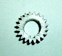
The following photos show a few other views of the finished project and a 20 tooth gear cut using it.
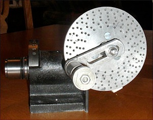
The photo above shows the side of the modified spin indexer with the hand crank and one of the fraction plates described in the Gingery book.
The photo to the left shows a 20 tooth gear I cut using the dividing head and my vertical milling machine, just to prove to myself that it works!